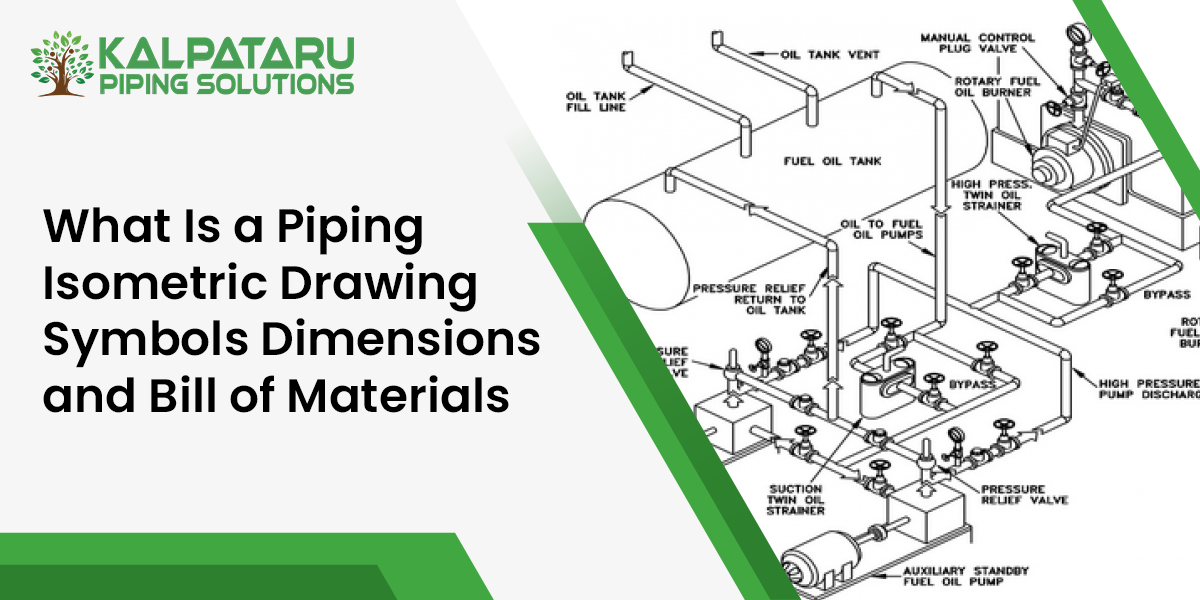
Piping isometric drawing is defined as one line graphical representation of pipe pipeline, which is created on 30-degree angle axes to provide three dimensional route in 2-D paper space. The drawing depicts the route, accessories and valves, dimensions and elevation levels, weld markers and material list for the construction process. The construction team relies on it, the inspection party checks it and the purchasing department in its turn places orders based on it.
Kalpataru Piping Solution provide all necessary pipes butt weld fittings and flanges and valves that appear in these drawings, which is the reason we read isometric drawings every day. This guide is intended to describe what is a piping isometric drawing, how piping isometric symbols work, what is the meaning of dimensions and notations, the process of reading piping isometric drawings step by step, comprehension of piping BOM and the process of turning drawing into pipe fabrication drawing, and it will finish with some common mistakes and a simple checklist.
What Is a Piping Isometric Drawing?
Think of a pipeline as a path through space. A piping isometric drawing shows its full route in one view, using three axes set 120 degrees apart. Vertical pipes remain upright, while the two horizontal directions are drawn at 30 degrees to the horizontal edge of the sheet.
Each pipe is shown as a single line, regardless of size. The drawing is not to scale, so always follow the written dimensions. One drawing usually covers one line number, and large plants may have hundreds of sheets.
The sample below shows a short four inch line with a gate valve, which we will use throughout this guide.
Isometric Drawing vs P and ID vs GA Drawing
People often mix these three drawings up, but each one answers a different question.
Drawing | What it shows | Scale | Who uses it |
P and ID | Process flow, equipment, valves and instruments | No scale and no routing | Process engineers and operators |
GA drawing | Layout of equipment and pipe in plan and elevation | Drawn to scale | Designers and site planners |
Piping isometric drawing | One pipe line with route, dimensions, welds and a bill of materials | Dimensioned, not to scale | Fabricators, inspectors and buyers |
In short, the P and ID tells you what the line must do, the GA drawing tells you where it goes in the plant, and the piping isometric drawing tells you exactly how to build it.
Piping Isometric Symbols
Piping isometric symbols are the short hand of the drawing. Instead of drawing every fitting in full, the designer uses a standard shape for each part. Learn the common ones and most drawings become easy to scan. The sheet below shows the simplified shapes used in this guide.
Item | How it appears | What it tells you |
Pipe run | A single heavy line | The route of the pipe, whatever its size |
Elbow | A bend in the line with a weld dot | A change of direction, usually 90 or 45 degrees |
Tee | A branch off the main line | A branch connection and its size |
Reducer | A tapered shape between two sizes | A change of pipe size, concentric or eccentric |
Flange | A short bar across the line | A bolted joint to a valve, nozzle or another pipe |
Gate, globe, ball and check valves | Two triangles or a triangle with a bar | The valve type, with a hand wheel or stem shown |
Shop weld | A filled dot | A weld made in the fabrication shop |
Field weld | An open dot, often with a flag | A weld made at site during installation |
Flow arrow | An arrow along the line | The direction of flow |
One caution matters here. Symbols are usually similar from one company to another, but they are not identical. The legend on the drawing, or on the project piping specification, always decides. For clear definitions of the parts themselves, see our guide to the types of pipe fittings, and for flange types read types of flanges, uses, materials and standards. The valve symbols are explained further in our guide to industrial valves, types, functions and applications.
Dimensions, Elevations and Notes
The numbers on the drawing are what turn a sketch into a build instruction. A few ideas cover almost everything you will see.
- Centreline dimensions. Lengths are normally measured from the centre of one fitting to the centre of the next, not from the outside edge.
- Elevations. Written as EL followed by a number, they give the height of the pipe above a fixed reference level. In our sample the line starts at EL 1500 and rises 2000 to reach EL 3500.
- Coordinates. Some drawings also give the position of key points on the plant grid, so the pipe can be placed exactly.
- North arrow. It fixes the direction of the drawing against the plant. Without it, nobody can tell which way a run is heading.
- Offsets and angles. Lines that run at an angle are shown with their offset dimensions, so the fabricator can work out the cut length.
- Notes. These cover insulation, painting, pressure test, material specification and any special instruction for that line.
Because the drawing is not to scale, never measure a length with a ruler. Read the number.
How to Read a Piping Isometric Drawing
Piping isometric drawing reading becomes simple when you follow a fixed order. Use the sample drawing above and work through these steps.
- Read the title block. Note the line number, the sheet number and the revision. Make sure you hold the latest revision.
- Find the north arrow. This tells you which direction each run is going.
- Find the flow arrow and the start point. In our sample the pipe starts at the left flange and flows east.
- Follow the line leg by leg. Read each dimension. Our line runs 4000 east, 2000 up, 4000 north and 3000 east.
- Check the elevations. The first leg sits at EL 1500 and the upper legs at EL 3500.
- Spot the fittings and valves. Count the elbows, find the flanges and locate the gate valve on the north run.
- Find the weld marks. Filled dots are shop welds and the open dot with a flag is the field weld.
- Match every balloon number to the bill of materials, so you know exactly what each part is made of and how many are needed.
- Read the notes last, for test, paint or insulation instructions.
Done in this order, even a busy drawing falls into place, and mistakes show up quickly because something will not match.
Piping BOM: Reading the Bill of Materials
The piping BOM is the table at the bottom of the drawing. It lists every item needed to build the line, and each balloon on the drawing points to one row. Without a clean BOM the purchase team cannot order and the shop cannot start.
Each column has a job:
- Item. The number that matches the balloon on the drawing.
- Quantity. How many pieces are needed. Pipe is often shown as a length or as a lot, because it is cut to size from the cut list.
- Size. The nominal size of the part, for example four inch.
- Description. The part name with its rating, end type and dimensional standard.
- Material. The material specification, such as ASTM A106 Grade B for carbon steel pipe.
In our sample, item 1 is the seamless pipe, item 2 is the three long radius elbows, item 3 is the two weld neck flanges, item 4 is the gate valve, item 5 is the gaskets and item 6 is the stud bolts. Every row ties back to a balloon, and every balloon ties back to a row. If one is missing, the drawing is not ready.
The standards named in the BOM tell you what to buy. Elbows and other butt weld fittings follow ASME B16.9, and flanges follow ASME B16.5. The material standard tells you what the part is made of. If you want to see how these standards split the work, read our guide to ASTM vs ASME standards for pipes, tubes and fittings.
The pipe row also deserves a closer look. Whether the line uses seamless or welded pipe changes the specification, and our comparison of seamless pipe vs welded pipe explains the difference. For the parts themselves, you can browse our pipe fittings range, our stainless steel pipe fittings and our stainless steel valves.
From Isometric to Pipe Fabrication Drawing
A pipe fabrication drawing is an isometric that has been broken down so the shop can build it. A long line is rarely built in one piece. It is cut into sections called spools, each small enough to be made in the shop, moved on a truck and lifted into place.
The spool drawing shows the cut lengths, the fittings, the shop welds and the ends where the spool will be joined to the next one at site. Those site joints are the field welds. Work done in the shop is easier to control, so designers try to make as many welds as possible in the shop and keep the field welds to a minimum.
Weld type | Where it is made | What it means on the drawing |
Shop weld | In the fabrication shop | Made before the spool leaves the shop |
Field weld | At the site, during installation | Marked so the site crew knows where the spool joins |
Field fit weld | At the site, with a length left for trimming | A pipe length is left long and cut to fit on site |
Butt welds are the most common joint on process lines, and the quality of the fitting at each weld matters. Our guide to butt weld fittings, features and applications explains the joint in detail.
Types of Piping Isometric Drawings
The same drawing goes through several stages in its life, and the level of detail changes at each one.
- Design isometric. Made during design to check the routing and to take material quantities.
- Fabrication or spool isometric. Broken into spools with cut lengths and weld marks for the shop.
- Installation isometric. Used at site to place spools and plan the field welds.
- As built isometric. Updated after construction to show what was actually installed.
Standards Behind the Drawing
Several standards sit behind a piping isometric drawing, but they do different jobs, so it helps to keep them apart.
Standard | What it covers |
ISO 6412 | Simplified representation of pipelines on technical drawings, including isometric views |
ASME B31.3 | Design and construction rules for process piping. It is a piping code and does not set out what an isometric must contain |
ASME B16.9 | Dimensions of factory made butt weld fittings |
ASME B16.5 | Dimensions and ratings of pipe flanges and flanged fittings |
Project piping class | The client rules for material, rating and parts on each line |
Always check the edition that your project calls for, because standards are revised from time to time.
How Isometric Drawings Are Made
Most isometrics today are generated from a three dimensional plant model, then checked by a person before issue. Software such as AVEVA, AutoCAD Plant 3D and SmartPlant 3D is widely used for the model. The tool matters less than the check. A drawing that has come out of a model can still carry a wrong dimension, a missing weld mark or an old revision, so a human review before release is always worth the time.
Frequently Asked Questions
A piping isometric drawing is a single line pictorial drawing of one pipe line, drawn on 30 degree axes. It shows the route, fittings, valves, welds, dimensions, elevations and a bill of materials, so the line can be fabricated, checked and installed without guessing.
No. A piping isometric drawing is dimensioned but not drawn to a true scale. The lengths on paper are proportionate so the layout is easy to follow, and the written dimensions are what the fabricator must use.
Start with the title block and line number, find the north arrow, then follow the flow arrow from the start point. Read each dimension and elevation, spot the fittings and valves, check the shop and field weld marks, and match every balloon number to the bill of materials.
A piping BOM, or bill of materials, is the table on an isometric that lists every item needed to build that line. It gives the item number, quantity, size, description and material, and it is the base for purchasing and for checking the finished spool.
A P and ID shows process flow, equipment and instruments with no routing or length. An isometric drawing shows the physical route of one pipe line with dimensions, welds and a bill of materials, so it is the drawing used to fabricate and install the pipe.
A spool drawing is a pipe fabrication drawing for one section of a line that is built in the shop and carried to site as a single piece. It shows the cut lengths, fittings, shop welds and the field weld ends where the spool joins the next one.
Reading the Drawing, the Welds and the BOM Together
A piping isometric drawing only works when three things agree. The route and dimensions must close, the weld marks must show who builds each joint, and the bill of materials must match every part on the page. Once you can read the symbols and follow the line from the start point to the end, you can catch errors long before they reach the shop floor.
If you are preparing a bill of materials and need pipes, butt weld fittings, flanges or valves for it, explore our full product range or get in touch with our team with your size, material and standard, and we will help you confirm the right specification.
Enquire Now
Related Blogs
What is Stainless Steel Valve?
What Is Monel Alloy? Composition, Properties & Uses (Guide)