
Inconel 625 Flanges Manufacturer & Supplier in India
Kalpataru Piping Solution is a trusted manufacturer, Inconel 625 flange supplier, stockist, and Inconel 625 flanges exporter, manufacturing flanges as per the ASTM B564 and ASME SB564 and dimensional standards like ASME B16.5, B16.47, and EN 1092-1. Made from nickel chromium molybdenum niobium alloy stock that is the same heat resistant, corrosion proof material used in offshore platforms, chemical processing plants, marine systems and aerospace, our Alloy 625 flanges, also known as UNS N06625 / WNR 2.4856, are precision formed from certified alloy stock. Our Nickel Alloy 625 flanges are also known as Alloy 625 Flanges and are available in all the standard flanges and can be dispatched on same day.
All the ASTM B564 Inconel 625 flanges supplied are traceable to heat and lot numbers with Mill Test Certificates (MTC) as per EN 10204 3.1 and can be third party inspected by TUV, Bureau Veritas, Lloyds and SGS. From single weld neck flange to bulk project quantity, we have ready stock of blind, slip on and RTJ flange to export it to 80 plus countries around the world from Mumbai, India. For the wider Inconel flange product range, see our Inconel Flanges hub or browse related Super Duplex Steel Flanges.
- What are Inconel 625 Flanges?
- Inconel 625 Flanges Specification
- Types of Inconel 625 Flanges
- Chemical Composition of Alloy 625 Flanges
- Mechanical Properties of Inconel 625 Weld Neck & Blind Flanges
- Physical Properties of Nickel Alloy 625 Flanges
- Equivalent Grades of Inconel 625 Flanges
- International Standards & HS Code of Alloy 625 Flanges
- Pressure Ratings & Classes of Inconel 625 Flanges
- Dimension Chart of Alloy 625 Slip On & Socket Weld Flanges
- Thickness of UNS N06625 Blind & Spectacle Blind Flanges
- Weight Chart of Inconel 625 Forged Flanges
- Flange Faces & Gasket Sizes of Alloy 625 Flanges (RF, FF, RTJ)
- Applications & Industries Using Inconel 625 Flanges
- FAQ’s About Inconel 625 Flanges
What Are Inconel 625 Flanges
Inconel 625 weld neck flanges and other flange types are high performance pipe connection components manufactured from Nickel Alloy 625, a nickel chromium molybdenum alloy strengthened by niobium and tantalum additions. Unlike standard stainless steel flanges, Inconel 625 flanges derive their exceptional strength from solid solution hardening rather than precipitation hardening, making them dimensionally stable across a wide temperature spectrum from cryogenic (minus 196 degrees Celsius) service all the way up to 982 degrees Celsius (1800 degrees Fahrenheit) continuous service.
The alloy’s outstanding resistance to pitting, crevice corrosion, intergranular attack, and chloride induced stress corrosion cracking makes UNS N06625 flanges the preferred choice wherever standard materials fail prematurely, including seawater piping, FGD scrubbers, sour gas lines, and aggressive acid service environments.
Specification of Inconel 625 Flanges
Parameter | Details |
Material Standard | ASTM B564 / ASME SB564 |
UNS Number | N06625 |
Werkstoff Nr. | 2.4856 |
Dimensional Standards | ASME B16.5, B16.47 Series A & B, B16.48, EN 1092-1, DIN, BS 10, BS 4504 |
Size Range | 1/2 inch (15 NB) to 48 inch (1200 NB) |
Pressure Classes | Class 150, 300, 400, 600, 900, 1500, 2500 | PN6 to PN160 |
Flange Face Types | RF, FF, RTJ, LJF, MF, TG, LMF, SMF |
Production Method | Forged, heat treated and precision machined |
Test Certifications | MTC EN 10204 3.1 | NABL Approved Lab | Third party inspection available |
HS Code | 75072000 |
Types of Inconel 625 Flanges
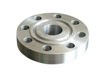
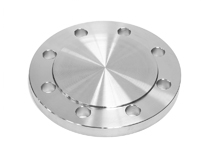
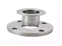
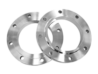
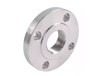
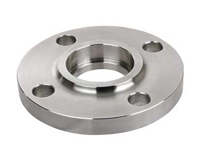
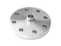
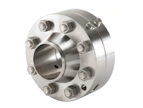
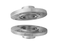
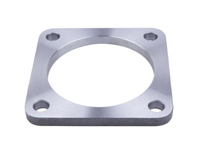
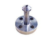
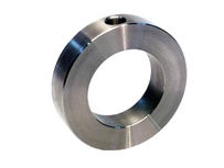
Review the diverse forms and flange types available in Inconel 625 Flanges, designed for versatile industrial connections and sealing requirements (existing product photography to be retained for each type):
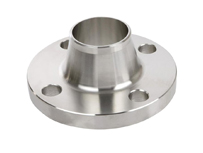
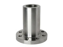
- Inconel 625 weld neck flanges (standard and long weld neck)
- Inconel 625 slip on flanges (raised face)
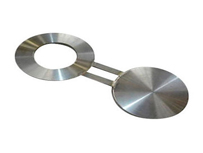
- Inconel 625 blind flanges and spectacle blind flanges
- Threaded (screwed) flanges
- Socket weld flanges
- Lap joint flanges
- Ring type joint (RTJ) flanges
- Reducing flanges
- Orifice flanges
- Tongue and groove flanges
- Square flanges, nipo flanges, bleed ring flanges, plate flanges
Chemical Composition of Inconel 625 / UNS N06625 Flanges
Element | Symbol | Min (%) | Max (%) |
Nickel | Ni | 58.0 | Balance |
Chromium | Cr | 20.0 | 23.0 |
Molybdenum | Mo | 8.0 | 10.0 |
Niobium + Tantalum | Nb+Ta | 3.15 | 4.15 |
Iron | Fe | N/A | 5.0 |
Carbon | C | N/A | 0.10 |
Manganese | Mn | N/A | 0.50 |
Silicon | Si | N/A | 0.50 |
Sulfur | S | N/A | 0.015 |
Aluminum | Al | N/A | 0.40 |
Titanium | Ti | N/A | 0.40 |
Cobalt | Co | N/A | 1.0 |
Mechanical Properties of ASTM B564 Inconel 625 Flanges
Property | Imperial (psi) | Metric (MPa or g/cm3) |
Tensile Strength (min) | 135,000 psi | 930 MPa |
Yield Strength – 0.2% offset (min) | 75,000 psi | 517 MPa |
Elongation (min) | 30% | 30% |
Hardness (Brinell max) | N/A | 220 HB max |
Density | 0.305 lb/in3 | 8.44 g/cm3 |
Melting Range | 2350 to 2460 deg F | 1290 to 1350 deg C |
Max Operating Temperature | 1800 deg F | 982 deg C |
The 220 HB max hardness rating confirms compliance with NACE MR0175/ISO 15156 requirements for sour service environments.
Physical Properties of Nickel Alloy 625 Flanges
Physical Property | Value |
Density | 8.44 g/cm3 |
Melting Point Range | 1290 to 1350 degrees C |
Specific Heat Capacity | 410 J/kg K (at 21 degrees C) |
Thermal Conductivity | 9.8 W/m K (at 25 degrees C) |
Electrical Resistivity | 1.29 microohm metres |
Modulus of Elasticity | 207 GPa (30 x 10 to the 6 psi) |
Coefficient of Thermal Expansion | 12.8 micrometres per m per degree C (21 to 538 degrees C) |
Inconel 625 / ASTM B564 UNS N06625 Equivalent Grades by International Standard
Alloy | UNS | WNR | EN | JIS | BS | AFNOR | GOST |
Inconel 625 | N06625 | 2.4856 | NiCr22Mo9Nb | NCF 625 | NA 21 | NC22DNB4M | ХН75МБТЮ |
International Standards & HS Code of Alloy 625 Flanges
Parameter | Details |
UNS Number | N06625 |
International Material Number | Werkstoff Nr. 2.4856 |
Material Specification | ASTM B564 / ASME SB564 |
HS Code | 75072000 |
Pressure Ratings & Classes of Inconel 625 Flanges (bar)
Working pressures in bar by ASME B16.5 pressure class, sorted in ascending temperature order.
Temp (deg C) | Class 150 | Class 300 | Class 400 | Class 600 | Class 900 | Class 1500 | Class 2500 | ||
-29 to 38 | 20.0 | 51.7 | 68.9 | 103.4 | 155.1 | 258.6 | 430.9 | ||
50 | 19.5 | 51.7 | 68.9 | 103.4 | 155.1 | 258.6 | 430.9 | ||
100 | 17.7 | 51.5 | 68.7 | 103.0 | 154.6 | 257.6 | 429.4 | ||
150 | 15.8 | 50.3 | 66.8 | 100.3 | 150.6 | 250.8 | 418.2 | ||
200 | 13.8 | 48.6 | 64.8 | 97.2 | 145.8 | 243.4 | 405.4 | ||
250 | 12.1 | 46.3 | 61.7 | 92.7 | 139.0 | 231.8 | 386.2 | ||
300 | 10.2 | 42.9 | 57.0 | 85.7 | 128.6 | 214.4 | 357.1 | ||
325 | 9.3 | 41.4 | 55.0 | 82.6 | 124.0 | 206.6 | 344.3 | ||
350 | 8.4 | 40.3 | 53.6 | 80.4 | 120.7 | 201.1 | 335.3 | ||
375 | 7.4 | 38.9 | 51.6 | 77.6 | 116.5 | 194.1 | 323.2 | ||
400 | 6.5 | 36.5 | 48.9 | 73.3 | 109.8 | 183.1 | 304.9 | ||
425 | 5.5 | 35.2 | 46.5 | 70.0 | 105.1 | 175.1 | 291.6 | ||
450 | 4.6 | 33.7 | 45.1 | 67.7 | 101.4 | 169.0 | 281.8 | ||
475 | 3.7 | 31.7 | 42.3 | 63.4 | 95.1 | 158.2 | 263.9 | ||
500 | 2.8 | 28.2 | 37.6 | 56.5 | 84.7 | 140.9 | 235.0 | ||
538 | 1.4 | 16.5 | 22.1 | 33.1 | 49.6 | 82.7 | 137.9 | ||
550 | N/A | 13.9 | 18.6 | 27.9 | 41.8 | 69.7 | 116.2 | ||
575 | N/A | 9.4 | 12.6 | 18.9 | 28.3 | 47.2 | 78.6 | ||
600 | N/A | 6.6 | 8.9 | 13.3 | 19.9 | 33.2 | 55.3 | ||
625 | N/A | 5.1 | 6.8 | 10.3 | 15.4 | 25.7 | 42.8 | ||
650 | N/A | 4.7 | 6.3 | 9.5 | 14.2 | 23.6 | 39.4 | ||
Dimension Chart of Alloy 625 Slip On & Socket Weld Flanges (ASME B16.5, Class 150)
All dimensions in inches.
NPS | Flange OD (O) | Raised Face Dia (R) | Thickness (Q) | Hub Base Dia (X) | Hub Bevel Dia (H) | Socket Depth (Z) |
1/2 | 3-1/2 | 1-3/8 | 7/16 | 1-3/16 | .84 | 3/8 |
3/4 | 3-7/8 | 1-11/16 | 1/2 | 1-1/2 | 1.05 | 7/16 |
1 | 4-1/4 | 2 | 9/16 | 1-15/16 | 1.32 | 1/2 |
1-1/4 | 4-5/8 | 2-1/2 | 5/8 | 2-5/16 | 1.66 | 9/16 |
1-1/2 | 5 | 2-7/8 | 11/16 | 2-9/16 | 1.90 | 5/8 |
2 | 6 | 3-5/8 | 3/4 | 3-1/16 | 2.38 | 11/16 |
2-1/2 | 7 | 4-1/8 | 7/8 | 3-9/16 | 2.88 | 3/4 |
3 | 7-1/2 | 5 | 15/16 | 4-1/4 | 3.50 | 13/16 |
4 | 9 | 6-3/16 | 15/16 | 5-5/16 | 4.50 | 15/16 |
6 | 11 | 8-1/2 | 1 | 7-9/16 | 6.63 | 1-1/16 |
8 | 13-1/2 | 10-5/8 | 1-1/8 | 9-11/16 | 8.63 | 1-1/4 |
10 | 16 | 12-3/4 | 1-3/16 | 12 | 10.75 | 1-5/16 |
12 | 19 | 15 | 1-1/4 | 14-3/8 | 12.75 | 1-9/16 |
14 | 21 | 16-1/4 | 1-3/8 | 15-3/4 | 14.00 | 1-5/8 |
16 | 23-1/2 | 18-1/2 | 1-7/16 | 18 | 16.00 | 1-3/4 |
18 | 25 | 21 | 1-9/16 | 19-7/8 | 18.00 | 1-15/16 |
20 | 27-1/2 | 23 | 1-11/16 | 22 | 20.00 | 2-1/8 |
24 | 32 | 27-1/4 | 1-7/8 | 26-1/8 | 24.00 | 2-1/2 |
Flange Drilling Chart (Bolt Pattern Data by Standard & Class)
| Standard | Class | Dia | No. Bolts | Bolt Circle Dia | Bolt Hole Dia | Bolt Size |
| AS4087 Flange | PN14 | 95 | 4 | 67 | 14 | M12 |
| ANSI B16.5 | ANSI 150 | 89 | 4 | 60 | 16 | 13 |
| ANSI B16.5 | ANSI 300 | 95 | 4 | 67 | 16 | 13 |
| ANSI B16.5 | ANSI 600 | 95 | 4 | 67 | 16 | 13 |
| ANSI B16.5 | ANSI 900 | 121 | 4 | 83 | 22 | 19 |
| ANSI B16.5 | ANSI 1500 | 121 | 4 | 83 | 22 | 19 |
| AS 2129 | Table C | 95 | 4 | 67 | 14 | 13 |
| AS 2129 | Table D | 95 | 4 | 67 | 14 | 13 |
| AS 2129 | Table E | 95 | 4 | 67 | 14 | 13 |
| AS 2129 | Table F | 95 | 4 | 67 | 14 | 13 |
| AS 2129 | Table H | 114 | 4 | 83 | 17 | 16 |
| AS 2129 | Table J | 114 | 4 | 83 | 17 | 16 |
| ISO 7005 (DIN) | PN6 | 80 | 4 | 55 | 11 | M10 |
| ISO 7005 (DIN) | PN10 | 95 | 4 | 65 | 14 | M12 |
| ISO 7005 (DIN) | PN16 | 95 | 4 | 65 | 14 | M12 |
| ISO 7005 (DIN) | PN20 | 90 | 4 | 60.5 | 16 | M14 |
| ISO 7005 (DIN) | PN25 | 95 | 4 | 65 | 14 | M12 |
| ISO 7005 (DIN) | PN40 | 95 | 4 | 65 | 14 | M12 |
Thickness of UNS N06625 Blind & Spectacle Blind Flanges (inches)
| NPS | OD | STD Wall | EXT Hvy | Sch 10 | Sch 20 | Sch 30 | Sch 40 | Sch 80 | Sch 120 | Sch 160 | XX Hvy |
| 1/2 | 0.84 | 0.109 | 0.147 | 0.083 | N/A | N/A | 0.109 | 0.147 | N/A | 0.188 | 0.294 |
| 3/4 | 1.05 | 0.113 | 0.154 | 0.083 | N/A | N/A | 0.113 | 0.154 | N/A | 0.219 | 0.308 |
| 1 | 1.315 | 0.133 | 0.179 | 0.109 | N/A | N/A | 0.133 | 0.179 | N/A | 0.25 | 0.358 |
| 1-1/4 | 1.66 | 0.14 | 0.191 | 0.109 | N/A | N/A | 0.14 | 0.191 | N/A | 0.25 | 0.382 |
| 1-1/2 | 1.9 | 0.145 | 0.2 | 0.109 | N/A | N/A | 0.145 | 0.2 | N/A | 0.281 | 0.4 |
| 2 | 2.375 | 0.154 | 0.218 | 0.109 | N/A | N/A | 0.154 | 0.218 | N/A | 0.344 | 0.436 |
| 3 | 3.5 | 0.216 | 0.3 | 0.12 | N/A | N/A | 0.216 | 0.3 | N/A | 0.438 | 0.6 |
| 4 | 4.5 | 0.237 | 0.337 | 0.12 | N/A | N/A | 0.237 | 0.337 | 0.438 | 0.531 | 0.674 |
| 6 | 6.625 | 0.28 | 0.432 | 0.134 | N/A | N/A | 0.28 | 0.432 | 0.562 | 0.719 | 0.864 |
| 8 | 8.625 | 0.322 | 0.5 | 0.148 | 0.25 | 0.277 | 0.322 | 0.5 | 0.719 | 0.906 | 0.875 |
| 10 | 10.75 | 0.365 | 0.5 | 0.165 | 0.25 | 0.307 | 0.365 | 0.594 | 0.844 | 1.125 | 1.0 |
| 12 | 12.75 | 0.375 | 0.5 | 0.18 | 0.25 | 0.33 | 0.406 | 0.688 | 1.0 | 1.312 | 1.0 |
| 14 | 14.0 | 0.375 | 0.5 | 0.25 | 0.312 | 0.375 | 0.438 | 0.75 | 1.094 | 1.406 | N/A |
| 16 | 16.0 | 0.375 | 0.5 | 0.25 | 0.312 | 0.375 | 0.5 | 0.844 | 1.219 | 1.594 | N/A |
| 18 | 18.0 | 0.375 | 0.5 | 0.25 | 0.312 | 0.438 | 0.562 | 0.938 | 1.375 | 1.781 | N/A |
| 20 | 20.0 | 0.375 | 0.5 | 0.25 | 0.375 | 0.5 | 0.594 | 1.031 | 1.5 | 1.969 | N/A |
| 24 | 24.0 | 0.375 | 0.5 | 0.25 | 0.375 | 0.562 | 0.688 | 1.219 | 1.812 | 2.344 | N/A |
| 30 | 30.0 | 0.375 | 0.5 | 0.312 | 0.5 | 0.625 | N/A | N/A | N/A | N/A | N/A |
| 36 | 36.0 | 0.375 | 0.5 | 0.312 | 0.5 | 0.625 | 0.75 | N/A | N/A | N/A | N/A |
Indicative Weight Chart of Inconel 625 Weld Neck Flanges (Class 150, ASME B16.5)
NPS (in) | OD (in) | Flange OD (in) | No. of Bolts | Approx. Weight (kg) |
1/2 | 0.84 | 3.50 | 4 | 0.45 |
1 | 1.32 | 4.25 | 4 | 0.91 |
2 | 2.38 | 6.00 | 4 | 1.82 |
3 | 3.50 | 7.50 | 4 | 3.63 |
4 | 4.50 | 9.00 | 8 | 5.90 |
6 | 6.63 | 11.00 | 8 | 10.43 |
8 | 8.63 | 13.50 | 8 | 17.24 |
10 | 10.75 | 16.00 | 12 | 27.22 |
12 | 12.75 | 19.00 | 12 | 38.56 |
14 | 14.00 | 21.00 | 12 | 50.35 |
16 | 16.00 | 23.50 | 16 | 64.86 |
18 | 18.00 | 25.00 | 16 | 81.65 |
20 | 20.00 | 27.50 | 20 | 102.06 |
24 | 24.00 | 32.00 | 20 | 145.15 |
Flange Faces & Gasket Sizes of Alloy 625 Flanges (RF, FF, RTJ)
NPS | Gasket I.D. | Gasket O.D. 150 LB | Gasket O.D. 300 LB | Gasket O.D. 600 LB | Gasket O.D. 900 LB |
1/2 | 0.84 | 1.875 | 2.125 | 2.125 | 2.50 |
3/4 | 1.06 | 2.25 | 2.625 | 2.625 | 2.75 |
1 | 1.31 | 2.625 | 2.875 | 2.875 | 3.125 |
1-1/4 | 1.66 | 3 | 3.25 | 3.25 | 3.50 |
1-1/2 | 1.91 | 3.375 | 3.75 | 3.75 | 3.875 |
2 | 2.38 | 4.125 | 4.375 | 4.375 | 5.625 |
2-1/2 | 2.88 | 4.875 | 5.125 | 5.125 | 6.50 |
3 | 3.50 | 5.375 | 5.875 | 5.875 | 6.625 |
4 | 4.50 | 6.875 | 7.125 | 7.625 | 8.125 |
6 | 6.62 | 8.75 | 9.875 | 10.50 | 11.375 |
8 | 8.62 | 11 | 12.125 | 12.625 | 14.125 |
10 | 10.75 | 13.375 | 14.25 | 15.75 | 17.125 |
12 | 12.75 | 16.125 | 16.625 | 18.00 | 19.625 |
Testing & Quality Control of Inconel 625 Flanges
Every Inconel 625 Flange manufactured and supplied by Kalpataru Piping Solution undergoes a rigorous multi stage quality control process:
Test Type | Method / Standard | Purpose |
Chemical Analysis (PMI) | OES / XRF Spectrometry | Verify alloy composition against ASTM B564 |
Mechanical Testing | Tensile, yield, elongation per ASTM E8 | Confirm strength meets spec minimums |
Hardness Testing | Brinell / Rockwell per ASTM E10/E18 | Check max hardness for NACE compliance |
Hydrostatic Test | ASME B16.5 Section 8 | Ensure no leakage under pressure |
IGC (Intergranular Corrosion) | ASTM A262 Practice E / C | Confirm resistance to sensitization |
Ultrasonic Testing (UT) | ASTM E114 | Detect subsurface defects in forging |
Magnetic Particle / Dye Penetrant | ASTM E709 / ASTM E165 | Surface crack detection |
Dimensional Inspection | ASME B16.5 tolerance check | Verify OD, bore, thickness, bolt circle |
Pitting Resistance Test | ASTM G48 Method A/B | Confirm PREN value and pitting resistance |
Corrosion Resistance Properties of Inconel 625 Flanges
Inconel 625 offers one of the broadest corrosion resistance profiles of any commercially available alloy, making it the flange material of choice in industries where failure is not an option:
Corrosion Type | Performance | Key Contributing Element |
General Corrosion | Excellent, resists a wide range of organic and inorganic acids | High Ni + Cr content |
Pitting Corrosion | Outstanding, PREN greater than 50 | Mo + Nb additions |
Crevice Corrosion | Excellent in chloride bearing environments | Mo content 8 to 10 percent |
Stress Corrosion Cracking (SCC) | Highly resistant in chloride media | High Ni (58% min) base |
Intergranular Corrosion | Excellent, Nb stabilizes grain boundaries | Niobium (Nb) |
High Temp Oxidation | Resistant to 982 degrees C (1800 degrees F) continuous | Cr protective oxide layer |
Seawater Corrosion | Excellent, widely used in offshore / marine applications | Mo + Ni combination |
Phosphoric Acid | Good, suitable for wet process phosphoric acid | Mo + Cr synergy |
Applications & Industries Using Inconel 625 Flanges
Inconel 625 flanges are specified wherever aggressive media, extreme temperatures, or chloride exposure rules out standard materials. Primary application environments include:
- Oil and Gas: Offshore platforms, sour gas lines, subsea manifolds
- Chemical Processing: HCl, HF, phosphoric acid service, chlor alkali plants
- Marine Systems: Seawater cooling, ballast systems, desalination plants
- Power Generation: FGD scrubbers, flue gas desulfurisation plants, nuclear coolant circuits
- Aerospace: Fuel and hydraulic systems requiring high temperature and corrosion resistance
- Cryogenic Service: LNG systems and applications down to minus 196 degrees Celsius
- Pharmaceutical & Food: High purity piping systems requiring corrosion free, hygienic flanged connections
Export Markets
Kalpataru Piping Solution exports Inconel 625 blind flanges, Inconel 625 slip on flanges, and the full flange range to clients across the Middle East, Europe, Southeast Asia, Africa, and the Americas, including key markets such as the United Arab Emirates, Saudi Arabia, the United Kingdom, Germany, Singapore, and the United States. For a shipment quote to your region, contact our export team.
Other Available Stock of ASTM B564 Inconel 625 Flanges
- Inconel 625 WNRF Flanges Dealer
- Alloy 625 Spectacle Blind Flanges Stockist
- Inconel Alloy 625 Long Weld Neck Flanges
- ASME SB564 Inconel 625 RTJ Flanges Supplier
- ANSI/ ASME B16.5 Inconel 625 Blind Ring Flanges
- B564 Inconel 625 BLRF Flanges Distributors
- Nickel Alloy 625 Lap Joint Flanges Trader
- SB564 Inconel 625 LJRF Flanges Manufacturer
- Inconel 625 Slip-on Raised Face Flanges
- Inconel 625 SORF Flanges Stockholder
- B564 Inconel Alloy 625 Screwed Flanges
- ANSI B16.5 Inconel 625 SWRF Flanges
- Inconel® Alloy 625 Reducing Flanges Stock
- Inconel 625 Tongue & Groove Flanges
- Inconel 625 EN 1092-1 Flanges in Mumbai
- Inconel 625 ASME/ANSI B16.5 Flanges
- ASTM B564 Inconel 625 Weldoflange
- Grade 625 Inconel Raised Face Flanges
- SB564 Inconel 625 Blind Raised Face Flange
- Inconel® 625 Forged Flanges Wholesaler
- B16.5 Inconel 625 Expander Flanges
- Inconel 625 Ring Spacers (Paddle Spacers)
- Inconel 625 Male & Female Flanges
- B564 Inconel 625 Flat Face Flanges
- Inconel 625 Flat Flanges Exporter
- Alloy UNS N06625 Flanges
- Inconel DIN 2.4856 Flange
- Inconel 625 High Hub Blind Flanges
- Inconel 625 ASME B16.5 Loose Flanges
- Inconel 625 BS 4504 Flanges
- Inconel 625 DIN Flanges in India
- Nickel Alloy 625 Flanges in Supplier
FAQ's About Inconel 625 Flanges
Yes. Inconel 625 can operate over a wide range, from cryogenic temperatures down to minus 196 degrees Celsius all the way up to 982 degrees Celsius (1800 degrees Fahrenheit) in continuous service. It resists oxidation and scaling at high temperature due to its protective chromium oxide film.
The high nickel content (58 percent minimum) protects against chloride induced stress corrosion cracking, and the niobium plus molybdenum additions strengthen the matrix to resist crack propagation. This makes Inconel 625 flanges the preferred choice in sour service, subsea, and acid environments where standard austenitic stainless would fail.
Yes. The alloy has very good weldability and can be joined by standard methods including TIG and MIG. Machining is possible but demands care, as the alloy work hardens; using rigid tooling and appropriate cutting speeds is recommended. Weld filler metal AWS A5.14 ERNiCrMo-3 is recommended for matching welds.
Grade 1 (annealed) is optimised for forming and ductility, typically used in lower temperature service. Grade 2 (solution annealed) provides higher strength and is specified for high temperature and elevated pressure applications above 593 degrees Celsius. Both are covered under ASTM B564, and Kalpataru supplies flanges in both conditions to order.
Standard supply includes EN 10204 3.1 Mill Test Certificates from a NABL approved laboratory, with PMI reports, dimensional inspection records, and heat traceability documentation. EN 10204 3.2 (third party witnessed) is available on request via TUV, Bureau Veritas, Lloyds, SGS, or DNV.
The Pitting Resistance Equivalent Number (PREN) for Inconel 625 is greater than 50, significantly higher than duplex stainless (PREN 30 to 40) and super duplex stainless (PREN 40 to 45). A higher PREN means the material is more resistant to pitting corrosion in chloride environments, which is why Inconel 625 is specified for seawater, FGD, and acid service applications where super duplex flanges would still be at risk.